A mulcher inspection before a large-scale job is more than a quick walk-around. High acreage work puts steady stress on the drive, teeth, cooling system, and structure for hours at a time. A single missed fault can mean hours of downtime in the middle of a weather window or contract deadline.
This guide turns the idea of a “once-over” into a structured sequence that catches early signs of wear, misalignment, or overheating before they cost you production.
The goal is to keep the machine stable, safe, and ready from the first row to the last pass of the day.
Powertrain and drive readiness
The drive is the heart of the mulcher, and in large-scale work it faces constant load for hours at a time. It must absorb sudden torque spikes when teeth hit dense wood or hidden debris. It must keep rotor speed stable even when the feed varies. And it must transmit power efficiently without overheating oil or slipping belts.
A healthy drive starts with the right protection devices. Shear bolts, torque limiters, and relief valves act as fuses, stopping destructive forces before they damage the motor, gearbox, or belts. Each device should be sized and maintained to match the head and carrier combination you are running.
Ratios also play a role in readiness. The gearing or pulley setup must balance torque and speed so the rotor can recover quickly after impact without bogging or overspeeding. This balance directly affects fuel use, chip quality, and component life.
Finally, fluid health is non-negotiable. Hydraulic oil must stay clean and within temperature limits to prevent seal failure, cavitation, and pump wear. That means checking filtration, breathers, and cooling systems before the first pass, not after the first sign of trouble.
Treat these elements, protection, ratios, and fluid condition, as core checks, not optional tasks. A drive that is strong, well-balanced, and clean will carry the machine through the day without costly interruptions.
Drive layout and protection systems
Different layouts handle shock in different ways. A belt drive can absorb impact, a direct motor responds quickly, and a gearbox offers torque control. Each needs its own checks before the first cut. The comparison in drive system differences will help match your inspection to the design you run.
Check shear bolts, torque limiters, and belt condition. Verify relief valve access and settings, following the build guidance in durability engineering so the drive structure is not the weak link.
Belt, coupling, or gearbox checks
Start warm and inspect under load. Cold checks hide problems. Heat reveals slip, drift, and weak points. Give the system a few minutes at working speed, then test and look with purpose.
Before the steps below, clear guards and plan a short no load run followed by a light bite. That pattern shows how the drive behaves when speed builds and when torque arrives.
- warm the carrier and head to operating temperature
- inspect belts for tension and alignment, or gearbox for oil level and leaks
- check for excessive vibration or noise during run up
- confirm case drain routing and flow rates for hydraulic drives
After the list, look deeper. On belt drives, check tension with the method your manual specifies, deflection or frequency, and confirm both sides match. Sight pulley faces with a straight edge. Glazing, black dust, or frayed edges point to slip or misalignment. Guards should refit without rubbing, which hints at correct alignment.
On direct couplings, inspect the hub, keys, and set screws. Look for witness marks that show movement. Check concentricity by watching the gap around the guard as the rotor spins down. Any wobble points to misalignment or looseness.
On gearboxes, read the sight glass at temperature, not cold. Wipe around seals and flanges, then look for fresh oil. Pull the magnetic plug if your layout allows, a light fuzz is normal, flakes are not. Smell the oil, a burnt smell points to heat or long change intervals.
For vibration, use your hands and your eyes. The head should come to speed smoothly, with no shake in the mounts, and spin down without scrape. A new buzz or a rising hum often appears before a failure. Note these changes and act before they grow.
For hydraulic drives, trace the case drain from motor to tank. Look for tight bends, heat scuff, or rub points. Measure case flow at temperature and record it. Rising case flow is an early sign of motor wear. Confirm relief settings with warm oil, then verify that the line to tank is free and cools as expected.
Finish by logging results for later comparison. Time to speed, operating pressure, oil temperature after a light pass, belt tension, gearbox level, case flow, and any noise notes. Small deviations often point to bigger problems down the road. These steps are quick, and they keep the drive from failing under continuous duty.
Motor and hydraulic circuit health
Hydraulics keep the rotor spinning. Any drift in pressure or flow shows up as reduced bite and uneven chips. Start warm. Read charge pressure, case drain, and main pressure at the test ports. Compare real numbers to your commissioning specs. A small mismatch can signal internal leakage, relief drift, or aeration.
Watch startup behavior. The head should reach speed smoothly without chatter. Listen for inlet whine, it hints at cavitation or a restricted suction line. Check return and charge filter indicators. A rising indicator after a short pass points to clogging or cold thick oil.
Measure case drain flow at temperature. Rising flow over days is an early sign of motor wear. Touch the case drain line carefully, it should be warm, not hot. Confirm anti cavitation checks are present and oriented correctly. Verify relief settings at temperature, not cold, then note the exact readings.
Inspect hoses and fittings. Look for rub marks, blisters, and heat discoloration near manifolds. Tight bends at the motor inlet raise inlet vacuum and invite cavitation. Secure clamps to stop vibration from sawing through an outer cover.
Cross check sensors. Compare in cab pressure and temperature to a manual gauge and an infrared spot at the cooler outlet. If displays do not match tools, adjust the inspection, not the thresholds.
Log everything the same way, every day. Record idle and working pressures, case drain flow, oil temperature after a pass, and any noise notes. Integrate those readings into your regular maintenance checklists so data is stored and easy to track. Trends tell the truth long before a failure does.
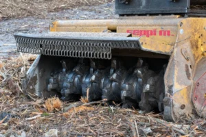
Cutting head and tooling
The cutting head must match the stand and the ground. Choose teeth for what you will actually cut, carbide for abrasive dirt and scattered stone, sharp steel for clean timber and fine finish. Keep the cutting angle true so teeth bite rather than rub. Use a retention system that locks hard and resists spin. Torque hardware to spec and mark it with paint so loosening is obvious. Balance matters on long jobs, replace teeth in opposing pairs, rotate positions to even wear, and check rotor runout during spin down. A straight, stiff rotor with consistent tooth height cuts smoother, runs cooler, and protects bearings.
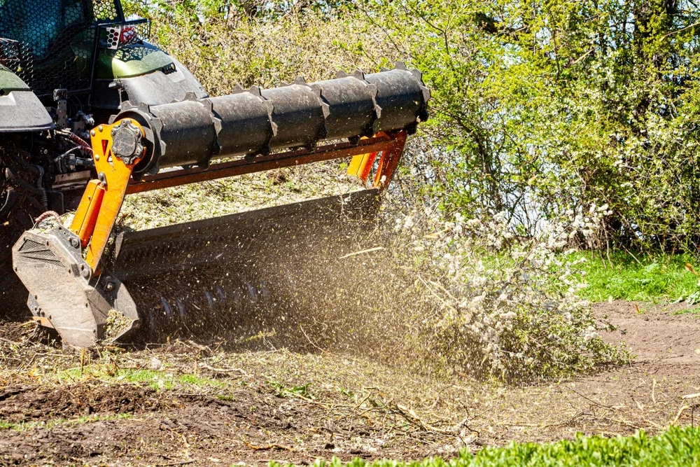
Control discharge from the start. Set the door, curtains, and deflectors so chips go down, not out. Feed with a steady bite and avoid crowding the door, since crowding raises throw and heat. On sensitive edges, shorten the bite and slow the advance. Keep guards intact and latching cleanly. Clear packed chips around bearing housings, since trapped debris cooks seals. Rope cutters and seal protectors keep vines and wire out of the ends. Plan a mid shift inspection on large blocks, retorque a sample tooth, wipe sightlines, and confirm chip flow is still controlled. This is how a head stays productive all day.
Tooth choice and retention
Tooth type affects both production speed and long-term durability. Carbide teeth handle abrasive, dirty stands where grit and stone are common. They resist wear but can leave a rougher finish. Sharp steel teeth excel in clean timber, cutting faster and leaving a finer surface, but they dull quickly in mixed or rocky ground. Matching tooth type to site conditions is one of the fastest ways to control downtime and tooth costs.
The full tradeoffs are outlined in choosing the right attachment. Before the mission, torque every tooth bolt to the specification in your manual, then mark them so movement is visible at a glance. Check wear indicators so teeth are replaced before they go blunt enough to overheat the rotor. Confirm all locking hardware is intact and seated correctly. A secure, sharp tooth keeps the rotor balanced, the cut smooth, and the drive running at its best.
Rotor balance and tooth pattern
An unbalanced rotor increases vibration, accelerates bearing wear, and wastes fuel. Over long jobs, that extra stress can lead to seal failure, loose hardware, or cracked mounts. Balance is not a one-time setup, it changes as teeth wear or are replaced.
Rotate the rotor slowly and check for even tooth spacing and consistent wear across all positions. Replace or rotate teeth in opposing pairs to keep mass distribution even. If wear is heavier on one side, adjust cutting habits to balance the load. Confirm all retention hardware matches the torque specifications in your manual, since over-tightening can distort mounts and under-tightening invites movement. A balanced head cuts cleaner, reduces strain on the drive, and extends bearing life, which in turn minimizes mid-job downtime and repair costs.
Guarding and discharge control
Guards, curtains, and deflectors are the first line of control for chip throw, and they protect both the operator and anyone near the work zone. They also shape the discharge so chips fall where you want them, reducing cleanup and damage to nearby surfaces. Every guard should latch securely and sit without gaps, since even a small opening can let high-velocity debris escape. Curtains need to hang straight with no frayed or missing links, and deflectors should hold their shape under load.
Before working near roads, trails, or property lines, confirm that your guarding setup matches the safety requirements in OSHA and ANSI mulcher safety standards. This ensures compliance and also improves control in tight buffer zones. Inspect guards at the start of each shift and after any contact with stumps, rocks, or dense brush. Replace or repair damaged sections immediately, since compromised guarding can turn a controlled operation into a liability.
Cooling and contamination control
Large jobs load the cooling pack all day. Fine fibers stick to warm cores fast. Screens must open without tools and seal properly after cleaning. Use reversible fans early, not after the gauge climbs. Keep ducting clear and straights short so air actually moves. Watch trend rate, not only peak temperature. A fast rise after a pass means airflow is falling, slow down, clean, and recheck before you continue.
Clean oil keeps pumps and motors honest. Check return and charge filter indicators at temperature. Replace weak breathers so the tank does not inhale dust overnight. Read magnetic plugs during service, light fuzz is normal, flakes are not. Sample oil on schedule and log the results. Secure clamps and sleeves where hoses can rub. Small steps here prevent heat, cavitation, and the failures that steal your afternoon.
Cooling system inspection
Mulching throws fine debris into the air, and it will clog cooling packs fast if airflow is restricted. Screens must be clean, fit tight, and seal fully so dust does not bypass the core. Any gap turns into a direct path for heat build-up.
Check the operation of reversible fans and run a cycle early in the day before heat climbs. Inspect ducting for bends, blockages, or buildup that could slow air movement. The debris patterns you see on dusty sites are similar to what we outline in rocky or uneven terrain, so keep those cleaning intervals in mind even if the ground looks clear.
Clean oil and filter health
Contaminated oil is one of the fastest ways to wear out pumps and motors. Fine debris, metal particles, or moisture in the hydraulic system act like abrasives, slowly cutting into internal surfaces until tolerances are lost. Once that wear starts, performance drops and failures become much harder to prevent. This is why oil inspection and filtration checks must be part of every operating cycle, not just a reaction to a problem.
- check return and charge filter indicators with the oil at working temperature, since cold readings can mask a restriction
- inspect breathers and replace them if airflow is restricted or if they are pulling in dust overnight
- drain and inspect magnetic plugs for metal fines, noting any sharp particles or flakes that may point to active component wear
Make these steps part of your long term care schedule so they are never skipped. Recording the results helps you spot trends, rising particle counts or frequent breather clogging can reveal issues before they turn into downtime. Consistency here is one of the lowest-cost ways to extend service intervals, maintain pressure stability, and protect high-value components from early failure.
Hose routing and abrasion prevention
Hoses that rub will fail mid-mission, often at the worst possible time. Even a small scuff can weaken the outer cover, letting heat, oil, and pressure do the rest. Once a hose bursts, you lose oil, production time, and in some cases, expensive components that ran dry.
Confirm that all clamps and abrasion sleeves are secure, positioned correctly, and not allowing movement at the contact point. Look closely for wear marks, blisters, or flattening, which signal that the hose is rubbing against a frame edge or another component. Pay special attention to areas where hoses pass near the rotor, boom pivots, or cooling packs, since vibration and heat are highest there.
Check for heat discoloration near manifolds or gearboxes. This can indicate restricted airflow or oil running hotter than normal, both of which shorten hose life. Correcting routing and securing clamps early prevents chafing, reduces the chance of mid-shift blowouts, and keeps the hydraulic circuit sealed and efficient.
“Most mid-job breakdowns started as a tiny change in pressure, temperature, or noise during pre-checks. When you catch it early, you save the whole day.”
Kyle Brennan, Senior Field Technician
Control, safety, and operator aids
Control systems, visibility tools, and diagnostics are as critical to uptime as the mechanical checks you make before the first pass. Well-designed controls give operators smooth, predictable response so they can adjust feed rate or head angle without overloading the drive. This reduces heat build-up, protects bearings, and helps maintain a clean cut.
Visibility tools such as cameras, work lights, and wipers let operators monitor discharge flow, check guarding, and see obstacles in poor light or dusty conditions. Clean sightlines are not only a productivity boost, they are a safety necessity, especially when working near roads, trails, or property lines.
Diagnostics take the guesswork out of troubleshooting. Pressure and temperature gauges in the cab, case drain flow meters, and clear fault codes give operators early warnings. When these readings are logged daily, they reveal trends before failures occur. Simple, accurate data, paired with an operator who knows how to read it, can prevent minor wear from turning into a major breakdown.
Control response and calibration
Lag or uneven response during startup often signals a hydraulic restriction, electrical fault, or calibration drift. Testing controls before you load the rotor is the fastest way to confirm everything is functioning as it should. Begin with the machine at operating temperature so valves, pumps, and electronics are working under real conditions. Cycle each control smoothly, noting any delay, hesitation, or unexpected surge in movement.
Verify that relief settings match the documentation provided for your specific head and carrier. A relief set too low will starve the rotor of power, while one set too high can stress hoses, mounts, and seals. Check that every switch, sensor, and safety interlock functions exactly as designed. An interlock that fails to stop the rotor or a switch that responds inconsistently can turn into a serious hazard on site. Completing these tests before the first bite gives operators a predictable machine and prevents control issues from interrupting production.
Visibility and camera systems
Poor visibility increases the risk of missed debris, uneven cutting, and safety incidents. The operator needs a clear view of the work zone, the discharge path, and any obstacles nearby. Dust, low light, and debris buildup can quickly limit that view if visibility tools are not maintained.
- clean and test all work lights so they provide even coverage of the cutting area and discharge zone
- wipe camera lenses and check video feeds for clarity and stable connection
- confirm wipers work if fitted for cab windows, and replace blades that streak or skip
Keeping these systems in top condition allows operators to stay informed even in dusty or low-light conditions. This improves accuracy, reduces the chance of striking hidden hazards, and helps maintain consistent cutting quality throughout the mission.
Sensor and gauge checks
Accurate readings let operators adjust before small issues grow. Warm the machine, then compare in cab readings to a calibrated manual gauge at the test ports. Check main pressure, case drain flow, and oil temperature at operating speed. Note any offset between the display and the tool, record it, and confirm it again after a short pass. If numbers drift, verify the sensor, the wiring, and the ground before you change any settings. Trust the tool first, then the screen, then the manual, in that order.
Test the instruments themselves. Tap the gauge lightly to rule out a stuck needle. Inspect connectors for moisture and dust, clean and reseat them so signals stay stable. Look for scuffed cables near manifolds and coolers, heat can harden insulation and cause noise in the signal. Set clear alarm thresholds for temperature and pressure, and review the trend lines during the pre start brief. Keep a known good handheld gauge in the service kit, label each test port, and log every reading the same way each day so you can spot drift early and act with confidence.
Get a pre-operation inspection plan
A large-scale mulching mission puts every system under stress. A tailored inspection plan ensures nothing gets missed, no matter who is on the job. This plan condenses key checks into a one page sheet for the cab, covering drive health, tooling, cooling, and safety systems. It includes bite and overlap rules, pressure and temperature targets, and cleanout schedules that fit your season and site type.
You can contact us for a ready-to-use pre-operation checklist designed for your carrier, head, and typical stand mix. It is a simple way to make mulcher inspections consistent, fast, and effective for every crew member.